|
|
BASIC MOTOR CONTROL AND RELAY LOGIC
Many machine functions involve turning motors on and off and/or reversing their direction. While there are many electronic motor controllers of all types on the market, if all one needs is to power a motor or other load on and off, an electromechanical relay is often all that is needed.
In order to understand and use relays in our designs, we must first understand the basics of switch logic. We all know that a switch is a device that opens and closes a circuit. "Off" is open, and "On" is closed. We also might be aware that in logic terminology, a closed switch represents a logic "1", and an open switch represents logic "0".
Switches are designated by the amount of poles and throws they have. The throws are the fixed contacts, while the poles are the contacts that move when the switch is activated or "thrown". Depending on how the switch is built it can have throws that are normally closed, meaning that they are in contact with the pole, closing the circuit; normally open, meaning the opposite, that the contacts are normally not in contact, or open; or the switch can have just about any number and configuration of poles and throws.
The typical nomenclature for switches abbreviates a "P" for poles and a "T" for throws, with the number of each also being abbreviated by a single letter. A common limit switch configuration, for example, would be "SPDT" for Single Pole, Double Throw.
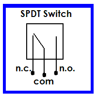 Also note that switches can be either "Momentary" or "Continuous" contact. A doorbell pushbutton switch is an example of a momentary contact switch. When the switch is not being pressed a spring returns the contacts to the "open" position. Therefore such a switch would be considered an SPST normally open pushbutton switch. The limit switch diagrammed here would also be a momentary switch. However, since it has two throws, the switch itself would not have a normally open or closed designation. Instead, the throws are identified by whether they are normally open or closed by the common notations of "n.o" and "n.c.", with the corresponding poles referred to as "common" and having the notation "com". Also note that switches can be either "Momentary" or "Continuous" contact. A doorbell pushbutton switch is an example of a momentary contact switch. When the switch is not being pressed a spring returns the contacts to the "open" position. Therefore such a switch would be considered an SPST normally open pushbutton switch. The limit switch diagrammed here would also be a momentary switch. However, since it has two throws, the switch itself would not have a normally open or closed designation. Instead, the throws are identified by whether they are normally open or closed by the common notations of "n.o" and "n.c.", with the corresponding poles referred to as "common" and having the notation "com".
For switches with more than two poles or throws, the number is given as a numeral such as "4PDT" for a Four Pole, Double Throw Switch. In the diagram, the dashed line indicates that all poles of the switch operate together. 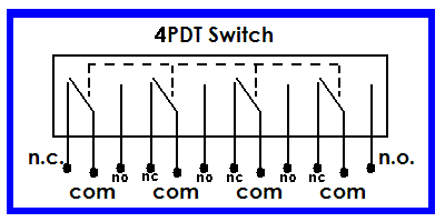
Relays
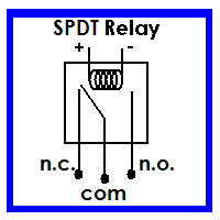 Relays are nothing more than electrically operated switches. Relays use an electromagnetic coil to pull the poles of the switch into position. Most relays return to the normally closed position by a spring when the coil is deenergized, so relay contacts are usually identified in the same way as those of a momentary contact switch. Relays are nothing more than electrically operated switches. Relays use an electromagnetic coil to pull the poles of the switch into position. Most relays return to the normally closed position by a spring when the coil is deenergized, so relay contacts are usually identified in the same way as those of a momentary contact switch.
Note that in the diagram the coil polarity is indicated. Relays will generally operate just as well regardless of coil polarity, however it does come into play for one important reason. Since a relay is an electromagnetic device, the coil generates what is known as flyback when it deenergizes. This is a phenomenon common to all inductive devices (which an electromagnet is). When the coil is deenergized the magnetic field surounding it collapses. This collapsing field cuts through the coil windings and induces a current in the opposite direction from that which charged the coil. This reverse current travels back through the wiring to the current source. If that source happens to be a logic gate, a microcontroller output, or some other sensitive device it can damage the device or otherwise cause it to malfunction.
For this reason it is common practice to place an ordinary diode across the coil terminals. Any normal diode will work. The diode allows current to charge the coil, yet it will block any reverse current. I have found that the easiest way to determine the proper polarity of the diode is to simply clip it onto the coil terminals and energize the relay. If it energizes, then the diode is aligned properly. If it does not, simply flip the diode around.
Simple DC Motor Control
Putting all of this together, here is a simple motor control circuit. The paramaters of this circuit design call for a single continuous contact switch (such as a basic wall switch or toggle switch) to activate a motor to drive a load to a certain limit. The load could be a gate opener, an elevator hoist, or a valve actuator, for example. We want the operator to drive the load to its limit, then stop and remain there until the switch opens, at which time the operator will return to its "home" position.
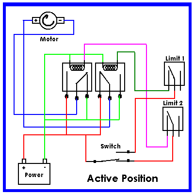
This particular control application can be accomplished with two SPDT momentary contact limit switches, two SPDT relays, and one SPDT toggle switch. Here is the circuit diagram:
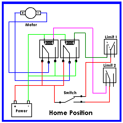 Let's analyze the circuit, starting with the two SPDT relays. These relays are configured in a reversing arrangement. If we follow the power and ground leads from the battery, we see that each normally closed position is connected to positive (+) and each normally open position is connected to ground (-). In this way the motor normally sees +12V at both leads. Since there is no net difference in potential, the motor remains stationary. In fact, since the motor leads are electrically connected, or shorted, in this arrangement it acts a brake to keep the motor from moving. This same arrangement has been used in golf carts and other motorized equipment to assist with braking. Let's analyze the circuit, starting with the two SPDT relays. These relays are configured in a reversing arrangement. If we follow the power and ground leads from the battery, we see that each normally closed position is connected to positive (+) and each normally open position is connected to ground (-). In this way the motor normally sees +12V at both leads. Since there is no net difference in potential, the motor remains stationary. In fact, since the motor leads are electrically connected, or shorted, in this arrangement it acts a brake to keep the motor from moving. This same arrangement has been used in golf carts and other motorized equipment to assist with braking.
Notice, though, that if either of the relays are activated, we get a connection to ground on that relay. If you trace the paths you will see that depending on which relay is activated the motor polarity will reverse. (You might also notice that if both relays are activated simultaneously we will see negative or ground at both motor terminals and again the motor will stop- however, this does not come into play in this example.)
What we have described thus far is a basic motor reversing cicuit that could be used in many robotic applications. The only real difference in how it is applied comes in how the relays themselves are controlled. For our example we have arranged limit switches to provide a specific behavior.
In this diagram, we see the circuit as it would be in the "home" position. The SPDT toggle switch is up, which is the "home" or "off" position for our purposes. For the sake of discussion, we will say that we are controlling a gate opener, and as we see it here the gate is in the closed position. We can see Limit Switch 1 in the activated position, the dashed line indicating that the normally closed position is now open. If we trace power from the battery, we see that it goes through the normally closed position of the toggle switch, up to Limit 1 where it is blocked because that throw is currently open (because the closed gate is resting against it.)
 Now let's say that we wish to throw the switch and open the gate. The next diagram shows the new positions of our switches and relays: Again tracing power from the battery we see the toggle switch now closed. Power has now been directed through Limit Switch 2 and on to the Left Side Relay, which has activated. In this position we see that our negative motor lead is now getting a connection to ground, so we see our motor rotating clockwise. (This direction is arbitrary- I could have shown it going the other way.) Our gate is now opening! Note that Limit Switch 1 would have changed positions the minute the gate started moving. The position of this switch no longer matters, though, since as you can see nothing else is connected to it at this point.
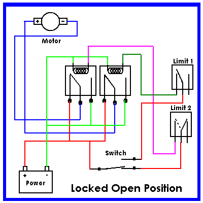 Next we see that our gate has fully opened. As it reached the end of its travel it contacted Limit Switch 2 and activated it. This in turn cut off power to the right side relay, which disconnected our ground connection to our motor shutting it off. Our toggle switch is still in the "on" position, which will hold our gate open as long as it remains in this position.
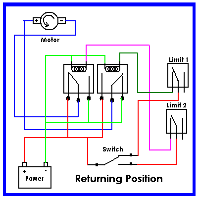 Finally, we decide to close the gate. By placing the toggle switch back in the "off" position, we route power back up to Limit 1, which is now in the normal position. We see that current can now flow through the normally closed throw to energize the Right Side relay. This connects ground to the positive side of our motor, and we see it indicated as moving in the counterclockwise direction. Our gate is now closing! Without the need for another drawing, we can see that the gate will continue to close until it once again contacts Limit Switch 1, at which time the ground connection through the Right Side Relay will be cut and the motor will stop, with everything back in the "Home" position. Finally, we decide to close the gate. By placing the toggle switch back in the "off" position, we route power back up to Limit 1, which is now in the normal position. We see that current can now flow through the normally closed throw to energize the Right Side relay. This connects ground to the positive side of our motor, and we see it indicated as moving in the counterclockwise direction. Our gate is now closing! Without the need for another drawing, we can see that the gate will continue to close until it once again contacts Limit Switch 1, at which time the ground connection through the Right Side Relay will be cut and the motor will stop, with everything back in the "Home" position.
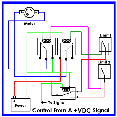 If your application called for the motors to be activated by a voltage signal instead of directly by a switch you would need only the replace the SPDT switch with a SPDT relay, then activate the relay with your signal voltage. The last diagram illustrates this. In this way you could control the gate with a remote control, or use the circuit to power a headlight door whenever it recieves voltage from the headlight circuit.
This is just one version of a motor reversing circuit. As you will find in many robotics projects, there is seldom only one "right way" to accomplish something. We could have used a single DPDT relay for reversing, with an additional power relay to turn the motor on and off. If we knew we were going to have the same relay coil voltage as the rest of our system, we could have tapped power from the throws of our relay back through the limit switches and into our relay coils to electrically "latch" the motors on. There are infinite variations of the example I gave here, and I encourage the reader to grasp the basics shown here then use your imagination to create your own control circuits.
Updated 12 April, 2008 |

 Let's analyze the circuit, starting with the two SPDT relays. These relays are configured in a reversing arrangement. If we follow the power and ground leads from the battery, we see that each normally closed position is connected to positive (+) and each normally open position is connected to ground (-). In this way the motor normally sees +12V at both leads. Since there is no net difference in potential, the motor remains stationary. In fact, since the motor leads are electrically connected, or shorted, in this arrangement it acts a brake to keep the motor from moving. This same arrangement has been used in golf carts and other motorized equipment to assist with braking.
 Also note that switches can be either "Momentary" or "Continuous" contact. A doorbell pushbutton switch is an example of a momentary contact switch. When the switch is not being pressed a spring returns the contacts to the "open" position. Therefore such a switch would be considered an SPST normally open pushbutton switch. The limit switch diagrammed here would also be a momentary switch. However, since it has two throws, the switch itself would not have a normally open or closed designation. Instead, the throws are identified by whether they are normally open or closed by the common notations of "n.o" and "n.c.", with the corresponding poles referred to as "common" and having the notation "com".
 Relays are nothing more than electrically operated switches. Relays use an electromagnetic coil to pull the poles of the switch into position. Most relays return to the normally closed position by a spring when the coil is deenergized, so relay contacts are usually identified in the same way as those of a momentary contact switch.
 Now let's say that we wish to throw the switch and open the gate. The next diagram shows the new positions of our switches and relays: Again tracing power from the battery we see the toggle switch now closed. Power has now been directed through Limit Switch 2 and on to the Left Side Relay, which has activated. In this position we see that our negative motor lead is now getting a connection to ground, so we see our motor rotating clockwise. (This direction is arbitrary- I could have shown it going the other way.) Our gate is now opening! Note that Limit Switch 1 would have changed positions the minute the gate started moving. The position of this switch no longer matters, though, since as you can see nothing else is connected to it at this point.
 Next we see that our gate has fully opened. As it reached the end of its travel it contacted Limit Switch 2 and activated it. This in turn cut off power to the right side relay, which disconnected our ground connection to our motor shutting it off. Our toggle switch is still in the "on" position, which will hold our gate open as long as it remains in this position.
 Finally, we decide to close the gate. By placing the toggle switch back in the "off" position, we route power back up to Limit 1, which is now in the normal position. We see that current can now flow through the normally closed throw to energize the Right Side relay. This connects ground to the positive side of our motor, and we see it indicated as moving in the counterclockwise direction. Our gate is now closing! Without the need for another drawing, we can see that the gate will continue to close until it once again contacts Limit Switch 1, at which time the ground connection through the Right Side Relay will be cut and the motor will stop, with everything back in the "Home" position.
 If your application called for the motors to be activated by a voltage signal instead of directly by a switch you would need only the replace the SPDT switch with a SPDT relay, then activate the relay with your signal voltage. The last diagram illustrates this. In this way you could control the gate with a remote control, or use the circuit to power a headlight door whenever it recieves voltage from the headlight circuit.
 , ,
, , 